
Why a load-bearing wall is an engineering problem first
A load-bearing wall carries weight from above – roof trusses, ceiling joists, a second floor, sometimes a masonry chimney – down to the foundation. When the wall is removed, every pound it was carrying has to travel a new path: into a beam, out to the beam ends, down through posts, and into footings that can take the concentrated load without settling. Each of those elements has to be sized for the real loads on that particular house, including wind and the live loads of people and furniture upstairs.
That is why the first person on a beam project should be a licensed structural engineer, not a welder or a framer. The engineer identifies which walls are actually bearing (it is not always obvious; interior walls running perpendicular to the joists are the usual suspects, but hip roofs and point loads change the picture), calculates the loads, and produces stamped drawings that specify the beam, the posts, the connections and the footings. In most Texas cities, the building department will not issue a permit for removing a bearing wall without those drawings.
W-beam, LVL or flitch beam?
The engineer chooses the beam type based on span, load and headroom. A laminated veneer lumber (LVL) beam is common for shorter spans and is installed by carpenters with no welding at all. A flitch beam sandwiches a steel plate between two pieces of lumber and is bolted through; it saves depth but still involves no field welding. A steel wide-flange beam (a W-shape such as a W8x18 or W10x26) is the choice for long open spans, heavy second-floor loads, or when the ceiling cavity is shallow. Steel beams are where welding enters the project, and the rest of this article focuses on them.
Permits, inspections and the stamped drawings
Removing a bearing wall is structural work, and nearly every Texas municipality – Houston, Dallas, Austin, San Antonio and their suburbs – treats it as permit-required. The permit package usually consists of the engineer’s stamped drawings and calculations plus a contractor’s application. The inspector will typically want to see the beam, posts and connections before they are concealed behind drywall, and may want to see the footings before concrete is poured. Unincorporated county areas can be looser, but your homeowner’s insurance and any future buyer’s inspector will still care whether the work matches an engineered design.
The stamped drawings are the contract for everyone on the job. They say what size the beam is, what the bearing plates are, how the beam connects to the posts, what weld sizes and bolt grades are required, and what the footing dimensions are. A welder who changes any of those details without the engineer’s written approval is taking on liability for the entire structure. A good mobile welder will ask to see the drawings before quoting and will build to them, not around them.
The load path: posts, footings and bearing plates
A beam is only as good as what it sits on. At each end the beam bears on a post – typically a steel tube column (HSS 4×4 or similar), a pipe column, or a built-up wood post – and the post bears on the foundation. On a slab-on-grade house, which describes most of the Houston and Dallas suburbs, the existing slab is usually not thick enough to take a concentrated post load; the engineer will specify a thickened footing or a pier that is cut into the slab and poured before the post goes in. On a pier-and-beam house, the post may land on a new concrete pier or on a reinforced section of the existing beam.
Bearing plates spread the load. A steel plate at the bottom of the post sits on the footing (often on anchor bolts or epoxy anchors), and a cap plate at the top of the post gives the beam a flat, full-width bearing surface. Where a steel beam sits in a pocket in a masonry or concrete wall, a bearing plate under the beam end keeps the flange from crushing the material below it. Bearing plates are specified by size and thickness on the drawings and are typically welded to the post in the shop or on site.
Where the welding comes in
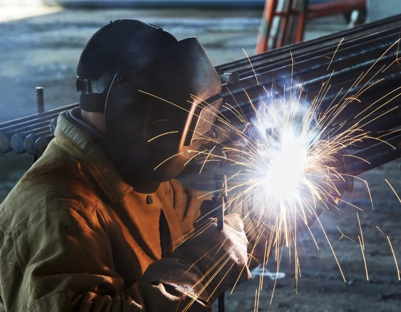
On a residential beam job the welding is concentrated at the connections. The common items are:
- Cap plates and base plates fillet-welded to steel columns, usually all around, with weld size called out on the drawings.
- Beam-to-column connections: the beam flange is welded to the column cap plate, or a seat angle and top clip are welded to receive the beam.
- Web stiffeners: short plates welded between the flanges at bearing points and under concentrated loads to stop the web from buckling.
- Splice plates when a beam is too long to get into the house in one piece and must be joined on site to engineered details.
- Hangers, clips and nailer attachments: joist hangers or a wood nailer bolted or welded to the beam so the floor or ceiling framing can be fastened to it.
Field welds versus bolted connections
Engineers frequently design residential connections to be bolted rather than welded, especially when the installer is a framing crew without a welder on staff. Bolted end plates and clip angles are forgiving, inspectable at a glance and need no fire watch inside a wood-framed house. Field welding is chosen when geometry is tight, when a stiffener or seat must be added after the beam is set, or when the engineer prefers a continuous welded connection for a moment frame (a frame that resists racking as well as vertical load). The drawing will show which it is; do not substitute one for the other.
When welds are specified, the usual reference is AWS D1.1, the structural welding code for steel. In practice that means a qualified welder, the correct process and filler (shielded metal arc with 7018 electrodes or flux-cored wire are typical on site), clean base metal, correct fit-up, weld sizes that match the drawing, and no undercut, cracks or porosity. Some jurisdictions and some engineers require special inspection of structural field welds by a third party. Ask before the welder leaves the site, because an inspector cannot evaluate a weld that is already buried in drywall.
What a mobile welder can do on site
A mobile welder brings the machine, gas, electrodes, grinders and fire protection to your driveway and works inside the house once the beam and columns are in position. Typical on-site tasks include welding cap and base plates to columns that were cut to length on site, adding stiffeners after the beam is set, welding splice plates on a two-piece beam, attaching seat angles, and welding a steel nailer to the beam flange. Columns and beams are usually cut and drilled in a shop beforehand because a 20-foot W10 is awkward to prep in a living room; a fabrication shop can pre-build posts with plates attached so the on-site work is minimal.
Welding inside an occupied wood-framed house is a fire-safety exercise. The welder should remove or wet down combustibles near the work, use welding blankets, keep a fire extinguisher at hand and maintain a fire watch for at least 30 minutes after the last arc. Ventilation matters too: galvanized plates and coated steel give off fumes that have no place in a closed room. All of this is routine for an experienced structural welder, but it is worth confirming before the truck arrives.
Does the welder need to see the engineer’s drawings?
Yes. Weld sizes, plate thicknesses and connection details come from the stamped drawings, and a welder who guesses at them is guessing with your roof.
Sequence of trades on a typical beam job
The order of work matters because each trade depends on the last one. A typical sequence looks like this:
- Engineer inspects, calculates and issues stamped drawings; contractor pulls the permit.
- Electrical, plumbing and HVAC in the wall are located and rerouted.
- Temporary shoring walls are built on both sides of the wall to carry the load while the wall is out.
- The wall is removed; footings are cut, formed and poured if required, then cured.
- Columns are set on base plates and the beam is lifted into position, shimmed and bearing checked.
- Field welds and bolts are completed; stiffeners and nailers added; the joists are hung from the beam.
- Inspection of the framing and connections; shoring removed only after the inspector signs off.
- Drywall, trim, flooring and paint.
Temporary shoring deserves emphasis. The house must be supported from the time the wall comes out until the beam is carrying load and the connections are complete. Shoring is usually two stud walls or a row of adjustable steel posts on a sill, placed a couple of feet either side of the wall, with blocking to spread the load over the slab. Removing shoring early, or shoring only one side of a wall that carries joists from both directions, is how ceilings sag and drywall cracks weeks later.
Common mistakes on residential beam projects
Skipping the engineer
Online span tables are written for uniform loads on simple spans. Real houses have point loads, hips, offset walls and prior remodels. A beam that is one size too small deflects, cracks finishes and, in the worst case, overloads the connections. A beam that is oversized wastes money and may not fit the ceiling. The engineer’s fee is small next to either outcome.
Posts landing on nothing
Placing a steel column on a four-inch slab with no footing is the most common structural failure we see in older remodels. The slab cracks and the post punches down a fraction of an inch, which is enough to drop the beam and open gaps above every door nearby. Footings are not optional because they are inconvenient.
Welds that do not match the drawing
Undersized fillet welds, welds skipped on the back side of a plate, or a bolted connection quietly replaced with a tack weld because the holes did not line up are all things an inspector will reject and an engineer will not sign off on. If a detail cannot be built as drawn, stop and get a written revision.
Mixing materials without a detail
Steel beams often connect to wood posts, and wood joists hang off steel beams. Every one of those transitions needs a specified fastener or bracket. Nailing a joist into a steel flange or resting a wood post directly on a beam end without a cap plate and strap is not a connection, it is a hope.
How Alpha fits into a beam project
Alpha Mobile Welding TX coordinates partner welders across Texas for the welded portions of residential and light-commercial beam installations: columns and plates, stiffeners, splices, seats and nailers, built to the engineer’s drawings with the fire protection a finished house requires. We do not size beams, pull permits or pour footings; your engineer and general contractor own those. If you have stamped drawings and a beam ready to set, send them to us and we will scope the welding, confirm partner availability for your address, and give you a straight estimate. If you do not have drawings yet, that is the first call to make.
Related services
Need a welder?
Send photos and your location and we will check partner availability and give you an estimate.